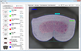
+ 86 - 20 - 3992 0957
English
HomeEquipmentSplice machines
SM Crimp V8 Advanced
SM Crimp V8 Advanced operation involves components manual positioning to the jig. Each jig is customized to the certain components. Jig is placed in the special support (fixture).
 
Fixture moves between loading and work positions automatically (by servomotor). These positions are predetermined to guarantee highly reliable connections.
 
Splice crimping is performed by pressing the pedal or automatically.
 
Tool cassette can be designed for a wide range of wire cross-sections, e.g. 0.5-1.5 mm2. What is more, changing only the cassette it is possible to perform various connections with the same splice band.
 
SPECIFICATIONS:
– digital crimp height adjustment with position controlled by encoder
– built-in CFM
– built-in component position video verification
– punch return to zero position by one touch
– using of several jigs for different components in one fixture
– possibility to mount high resolution external camera for components position, presence, colors, etc.
 

SPLICE CRIMPING

Technical characteristics
  • Power supply
    220-240 V (110 V available) / 50 Hz / 2A
  • Absorbed power
    approx. 500 watts
  • Motor rating
    300 watts
  • Cycle time
    Depends on product
  • Stroke
    35 mm
  • Crimping range
    35 mm
  • Noise level
    < 75 dB
  • Weight
    80-90 kg
  • Dimensions (WxDxH)
    375 x 660 x 490 mm
  • CE conformity
  • Apave (TÜV) certification

STANDARD FEATURES
  • Automated YZ fixture table
    Automated YZ fixture table

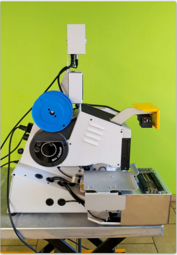
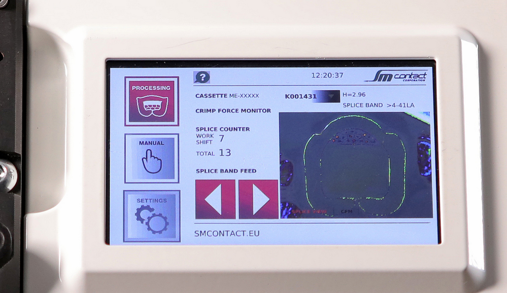
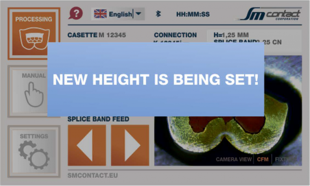
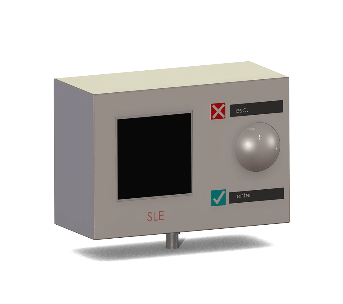
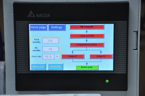
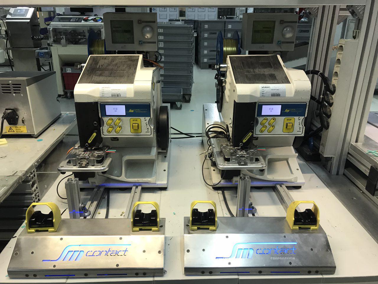
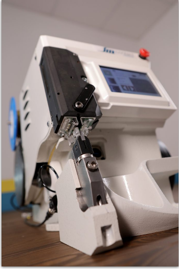
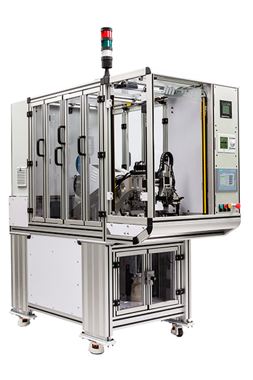
    Enables shifting the jig with components to the zone of crimping with Y and Z axes capability. High movement accuracy is achieved through programmable actions. Control over the YZ table is provided at the HMI screen, including control of stepper motor drives of the table.


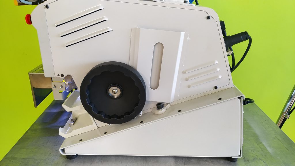
    Operator is protected by safety covers.


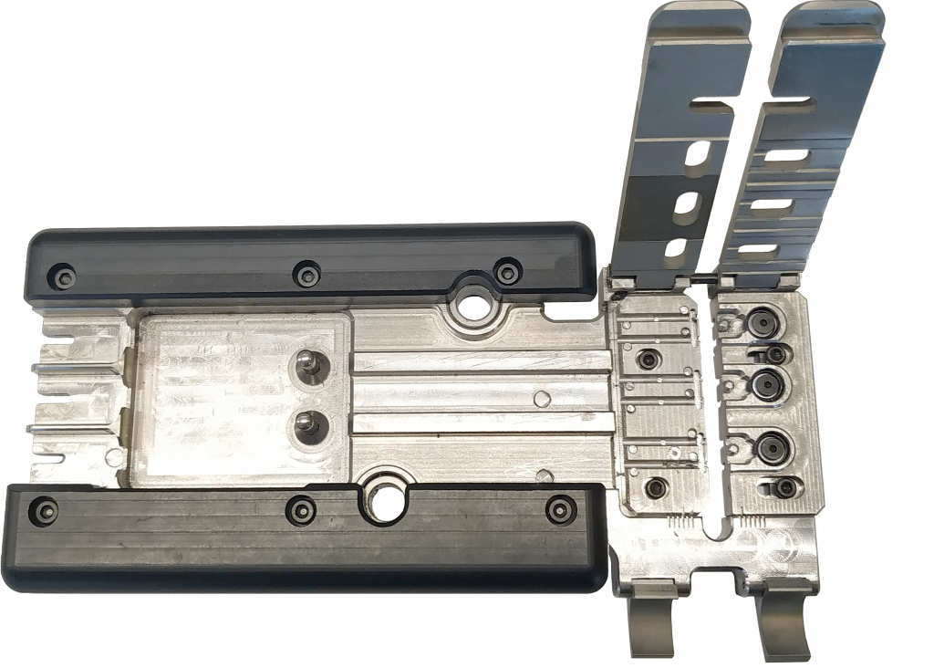
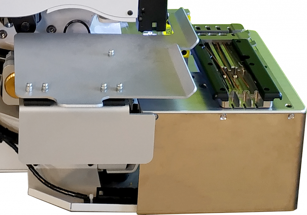
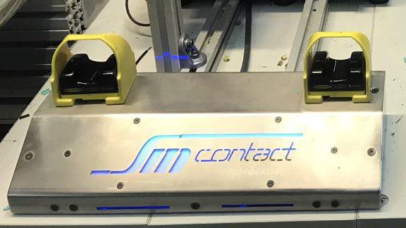
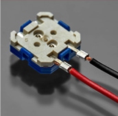
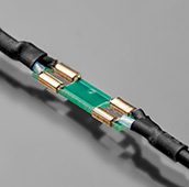
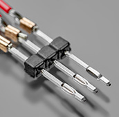
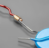
    Support for the jig precisely carries the jig to the crimping zone.


  • Touch screen control panel
    Touch screen control panel

    All controls except the power switch are located at the display. With 5 buttons and 1 display it is possible to control the quantity of products, inputs and outputs, interface language, tooling technical data, feeding system and activate emergency stop.


    It indicates the process of each crimp in a jig.


  • Motorized splice band feeding system
    Motorized splice band feeding system
    Rubber surface of a feeding wheel prevents damages of the splice band. Special sensor controls the length of each splice.
  • Built-in Crimp Force Monitor (CFM)
    Built-in Crimp Force Monitor (CFM)

    CFM captures, calculates and evaluates force-time curve and detects any deviation from the quality tolerances.

    System works with many types of splicing and crimping machines and suites well to any application requiring inline monitoring of forces.

    The reference curve of CFM corresponds to crimping force, but in fact it can reflect such quality deviations as:


    • missing wire strands,

    • missing terminal,

    • inaccurate components positioning,

    • inaccurate crimp height,

    • inaccurate wire gauge,

    • insufficient insulation strip length,

    • insulation in wire barrel,

    • wire partially inserted in wire barrel.


    CFM allows to adjust automatic cutting and/or rejection of defective items.


  • Crimp height adjustment
    Crimp height adjustment
    Motorized crimp height adjustment is realized via touch screen with buttons +- (increment of 0.01 mm) or by selecting among preadjusted connections parameters (automatically).
  • Jig
    Jig

    Removable part of a fixture that perfectly fits components and thus enables its precise positioning. Jig can be adapted to components depending on its quantity, shape, materials.


    If machine has two jigs, while one is processing, second can be reloaded by another operator.


  • Cast iron frame
    Cast iron frame
    In contrast to the machines assembled from separate parts by screws, SM Crimp cast iron frame warrants a perfect stability during crimping.
  • Splice band
    Splice band

    Splice band is defined according to the type of application and environment temperature range: splice band type and material (brass, brass with tin coating, cupronickel,cupronickel with tin coating, stainless steel), thickness (0.2 – 0.53 mm), width (1.5, 2, 3, 4, 6, 7 mm), and length.

    Splice band is engineered with serrations for magnet wire and standard wire types. It is suitable for multi-strand and solid core copper and aluminum wires.

    Our splice materials meet the following standards:


    • UL 486C

    • MIL – STD 202

    • IEC 60352-2

    • IPC/WHMA-A -620

    • REACH & RoHS


    SPLICE MATERIAL APPLICATION
    Brass CuZn30 General purpose, -80..+120°C
    Brass with tin coating CuZn30 tinned General purpose, -80..+120°C, corrosion resistant, pre-soldered components
    Cupronickel CuNi9Sn2 High reliability, -80..+400°C, perfect corrosion resistant, weldable
    Cupronickel with tin coating CuNi9Sn2 tinned High reliability, -80..+120°C, perfect corrosion resistant, weldable
    Stainless steel 2 mm: 2.4867, 4.6 mm: 1.4567 Special purpose, -80..+900°C, for aggressive environments
    Customer specified On request

  • Hand wheel
    Hand wheel
    Hand wheel is used to perform manual cycle for testing the system before production, i.e. centering the clincher, change of tooling. Wheeling moves the punch down and allows to monitor splicing process in general as well as positioning of the tooling.
  • Crimping tooling set
    Crimping tooling set

    Tooling set includes clincher, anvil, punch, punch guide, and cutting block.


    Such parameters as clincher type, clincher size, and punch tip shape are customized for the application.


    Inclined clincher surface, smooth cutting surface, quick-change tooling cassette, and finger guard lighting cap guarantees efficient & safe operation.


    Data memory in each tooling cassette stores its own tooling list (PN’s) and connection data for up to 10 connections with independent crimp height settings. It enables automatic correction of crimp height when the cassette is installed.


OPTIONS
  • Force sensor for CFM
    Force sensor for CFM
    Piezo sensor detects force at the moment of splicing, transmits information to CFM for data processing and displaying force-time curve corresponding to crimp force.
  • Protection of operation area
    Protection of operation area
    Safety covers can be installed on the side panels to detect foreign object presence and stop the machine.
  • Bimanual cycle start
    Bimanual cycle start
    Requires two hands touch to start the cycle to eliminate hands presence in the work zone.
  • POKA YOKE
    POKA YOKE
    Allows controlling utilization of NG/NOK components. If CFM detects quality deviation and estimates connection as NG/NOK, then machine stops operation and waits until NG/NOK component is placed to POKA YOKE bin.
  • Components camera control
    Components camera control
    According to the selected program, high/low definition camera takes picture and controls components` position, color and stripping length. High or low definition is selected depending on size of components.
  • HMI
    HMI

    On the touch screen display HMI system shows complete work algorithm, indicating the current step and step when the failure occurred if any. It can be displayed as an algorithm graphics or product visualization.


    HMI provides intuitive process control. It is possible to readjust all sensors including CFM to another product by choosing the corresponding program in the interface. HMI displays pictures of connections kept in memory when the tooling cassette is installed and the corresponding connection selected for processing.


    Within the password protected area one can switch machine subfunctions on/off. Different access levels (operator and technician) are available at HMI touch screen.


  • Double crimping
    Double crimping
    Two machines are used: one set up for one splicing type, another – for the second. This solution speeds up the process and perfectly fits if the product consists of different sized crimping.
  • Frame & cabinet
    Frame & cabinet
    Machine and all its components can be integrated into the floor mount frame for products needs.
  • Component position video verification
    Component position video verification

    Camera shoots the clincher area and sends video to the HMI screen in real time. Thus, operator can view the components being crimped and is capable to position them in the clincher precisely.


    There are two options for the camera placement:


    1, built into the tooling cassette,


    2, mounted on the left wall of the tooling cassette and connected via USB cable.


  • Quality control equipment
    Quality control equipment
    Laboratory equipment allows to control whether the splice quality matches industry norms or any other special requirements. Check our micrograph laboratories, pull force and crimp height control tools, as well as specialized measurement software.
APPLICATION FIELDS
COMPONENTS TYPES
  • ALTERNATIVE ENERGY
    ALTERNATIVE ENERGY
    ALTERNATIVE ENERGY
  • AUTOMOTIVE
    AUTOMOTIVE
    AUTOMOTIVE
  • CIVIL ENGINEERING
    CIVIL ENGINEERING
    CIVIL ENGINEERING
  • ELECTRONICS
    ELECTRONICS
    ELECTRONICS
  • LIGHT INDUSTRY
    LIGHT INDUSTRY
    LIGHT INDUSTRY
  • MASS MARKET
    MASS MARKET
    MASS MARKET
  • MEDICAL
    MEDICAL
    MEDICAL
  • RAILWAY
    RAILWAY
    RAILWAY
  • CORDS
    CORDS
    CORDS
  • DIODE & RESISTOR
    DIODE & RESISTOR
    DIODE & RESISTOR
  • FILAMENT
    FILAMENT
    FILAMENT
  • WIRE & CAPACITOR
    WIRE & CAPACITOR
    WIRE & CAPACITOR
  • WIRE & COIL
    WIRE & COIL
    WIRE & COIL
  • WIRE & DIODE
    WIRE & DIODE
    WIRE & DIODE
  • WIRE & LEADFRAME
    WIRE & LEADFRAME
    WIRE & LEADFRAME
  • WIRE & METALTAB
    WIRE & METALTAB
    WIRE & METALTAB
  • WIRE & PCB
    WIRE & PCB
    WIRE & PCB
  • WIRE & SENSOR
    WIRE & SENSOR
    WIRE & SENSOR
  • WIRE & RESISTOR
    WIRE & RESISTOR
    WIRE & RESISTOR
  • WIRE & WIRE
    WIRE & WIRE
    WIRE & WIRE
  • PCB & COAXIAL CONNECTOR
    PCB & COAXIAL CONNECTOR
    PCB & COAXIAL CONNECTOR
  • WIRE & PIN
    WIRE & PIN
    WIRE & PIN
  • WIRE & PLASTIC CONNECTOR
    WIRE & PLASTIC CONNECTOR
    WIRE & PLASTIC CONNECTOR
  • WIRE & PLUG ADAPTER
    WIRE & PLUG ADAPTER
    WIRE & PLUG ADAPTER
  • WIRE & THERMAL FUSE
    WIRE & THERMAL FUSE
    WIRE & THERMAL FUSE
  • SM CONTACT FRANCE
    Headquarters est. 1986
    +33 (0) 1 64 63 66 66
    Fax +33 (0) 1 64 63 67 22
    smcontact@smcontact.eu
    20-22 voie Gallo Romaine
    77860 Quincy-Voisins, France
  • SM CONTACT ASIA
    Asian subsidiary est.2008
    +86 20 3992 0957
    info@smcontact.cn
    #5-#8, building A7,Huachuang Industrial
    Park,9 Huateng RD, Shiji Town,
    Panyu District,Guangzhou,China
  • SM CONTACT ENGINEERING
    Russian & CIS subsidiary est. 2011
    +7 (812) 980 97 93
    info@smcontact.ru
    21 lit. A Basseynaya Street
    196191 Saint Petersburg, Russia
  • SM CONTACT GmbH
    German subsidiary est. 2015
    +49 89 693 30812
    sales_de@smcontact.eu
    Alte Landstrasse 25
    D-85521 Ottobrunn, Germany
  • SM CONTACT SPAIN
    Spanish subsidiary est. 2017
    +34 645 22 62 37
    smcontact@smcontact.eu
    Carrer de Vilafranca, 7
    08024 Barcelona, Spain
  • SM CONTACT TECH
    Baltic subsidiary est. 2018
    +372 56 829 870
    orders_smct@smcontact.eu
    Kadastiku 57A
    21004 Narva, Estonia
  • Guangzhou Geulu Equipments for Electronic Products Co,Ltd
  • #5-#8, building A7 Huachuang Industrial Park , 9 Huateng RD, Shiji Town, Panyu Dist, Guangzhou , China
  • +86- 20-3992 0957

    info@smcontact.cn

    www.smcontact.cn

© SM Contact 2019 粤ICP备20018780号
PARTNER ACCESS
I have read the Privacy and Cookies policy and consent to the collection, processing and use of my personal data.
PARTNER REGISTER
I have read the Privacy and Cookies policy and consent to the collection, processing and use of my personal data.
*Required fields
REGISTER